Related News
- 00
0000-00
How to Specify a Quay Crane for Container Terminals by Vessel Size and Throughput? - 00
0000-00
Which Bulk Handling Equipment Suits High-Moisture Cargo? - 00
0000-00
Terminal Automation Technologies That Raise Container Throughput Without Yard Disruption - 00
0000-00
Planning Offshore Dredging Operations: Key Risks, Methods, and Project Controls - 00
0000-00
Where Do Automated Guided Vehicles Deliver the Fastest Warehouse Gains in the Middle East?
Selecting PLC Control Systems for Reliable, Scalable Manufacturing Lines
Selecting PLC control systems begins with defining the control boundary of the line, not with comparing processor catalog specifications. A PLC that performs well on a small conveyor cell may become difficult to maintain when the line adds servo stations, vision inspection, safety zones, batch tracking, energy monitoring, or links to a warehouse and production execution layer. The selected architecture must maintain predictable response times under normal production load, fault recovery, and future expansion.
For a reliable manufacturing line, the PLC is part of a control stack rather than an isolated controller. Its practical value depends on the quality of its I/O topology, network behavior, electrical installation, programming structure, safety design, and lifecycle support. A sound selection process therefore starts with the motion, process, material-handling, and data requirements that exist at the machine level.
Define the Control Load Before Comparing Hardware
A processor selection should be based on the work performed during each scan or task cycle. This includes discrete I/O evaluation, analog signal conditioning, PID loops, servo coordination, communications servicing, alarm handling, data logging, and interface routines. A simple count of I/O points is insufficient. Two lines with the same point count can place very different demands on a controller when one line contains high-speed registration, synchronized axes, temperature zones, or intermittent communication with multiple intelligent devices.
Separate control functions by their timing sensitivity. Emergency stop functions and safety interlocks belong in an independently designed safety function architecture. High-speed motion, registration sensors, encoder capture, and fast reject mechanisms may require deterministic tasks with tightly bounded update intervals. Tank level control, heating zones, compressed-air monitoring, and production counters usually tolerate slower execution. Supervisory reporting, recipe transfer, and historian traffic should not consume resources needed for machine control.
Request an application-specific performance estimate rather than accepting a generic scan-time statement. The estimate should reflect the anticipated program size, communication connections, remote I/O update periods, motion axes, safety logic, and diagnostic services. It should also include a reasonable capacity margin. Excessive processor utilization can produce intermittent faults that are difficult to reproduce, particularly when network traffic increases during startup, a device reconnects, or an alarm burst occurs.
I/O Architecture Determines Much of the Real Installation Cost
Centralized I/O may be appropriate for compact equipment with short cable runs and a single electrical enclosure. It simplifies physical inspection and can reduce the number of field network components. On a long packaging, assembly, bulk-handling, or process line, distributed I/O often produces a cleaner installation. Sensors and actuators can terminate in local panels, reducing multi-core cable length, cable-tray congestion, voltage-drop concerns, and time spent tracing conductors during commissioning.
Distributed I/O introduces its own engineering requirements. Each field enclosure needs suitable power distribution, circuit protection, earthing, environmental sealing, network routing, labeling, and service access. The local supply must withstand the inrush and switching behavior of solenoids, valve islands, relays, and other connected loads. A remote I/O station that loses voltage because its supply was sized only for steady-state demand can appear as an unpredictable communications failure.
- Group I/O by machine function and physical location so that a fault can be isolated without searching through unrelated points.
- Reserve channels for expected additions, but avoid installing large unused racks where unused capacity creates avoidable enclosure size, power, and thermal load.
- Use signal types appropriate to the environment. Shielded analog circuits, encoder wiring, thermocouple extensions, and high-frequency pulse signals need routing discipline that differs from ordinary discrete wiring.
- Confirm that output modules match the load characteristics, including DC solenoids, AC contactor coils, proportional valves, relay interfaces, and any inductive suppression requirements.
Material handling and heavy-duty environments require particular care around connector selection and mounting. Vibration can loosen poorly retained terminals. Dust, washdown, salt-bearing air, oil mist, and temperature variation can affect enclosure integrity and corrosion behavior. Cable entries, gland plates, and drain arrangements should be considered alongside controller specifications; field wiring failures often account for more downtime than processor faults.
Communication Protocols Need a Defined Role
PLC control systems commonly communicate with drives, remote I/O, safety devices, HMIs, barcode readers, vision equipment, intelligent instruments, and upper-level software. A single network can sometimes support several of these functions, but combining every device on one unmanaged segment can turn a minor connection problem into a line-wide disturbance. The network design should distinguish between real-time control traffic, safety communication where applicable, engineering access, and business or supervisory data exchange.
Protocol selection should be driven by required behavior. Deterministic cyclic exchanges are suited to remote I/O, drive commands, synchronized motion, and interlocking signals. Acyclic messaging is suitable for parameter reads, diagnostics, recipes, and maintenance records. Data exchange with supervisory applications may use gateways, industrial middleware, or standard interfaces, but these paths should be buffered so a slow external system cannot delay a control task.
Assess device interoperability at the level of actual functions, not merely network compatibility. A drive may communicate successfully while exposing only basic start, stop, speed reference, and fault data. If the line needs torque limits, speed feedback, energy readings, safe torque functions, or detailed alarms, verify that the required parameters are available in the intended configuration. Similar checks apply to intelligent sensors, weighing equipment, RFID systems, and robotic cells.
Network drawings should show physical media, ports, managed switches, power sources, VLAN or segmentation boundaries where used, device names, and recovery behavior. A logical network diagram alone does not reveal whether two redundant paths share the same cable tray, power supply, or enclosure.
Availability Is Designed Through Failure Containment
Redundancy is justified only when the consequences of a failure and the recovery process support its cost and complexity. A redundant controller pair may be appropriate where an uncontrolled shutdown creates substantial process risk or recovery time. In many manufacturing lines, a well-documented spare processor, backed-up application, replaceable memory, labeled wiring, and tested restoration procedure may provide a more proportionate response.
Consider each failure domain separately: controller, power supply, network path, remote I/O island, field power, drive, sensor, and safety circuit. Adding a second PLC does little for availability if both controllers depend on one incoming supply, one network switch, or one remote I/O head. Conversely, duplicating every component can complicate troubleshooting and create additional configuration drift.
Recovery behavior deserves explicit review. After a power interruption, determine which outputs remain de-energized, which process values are retained, whether drives require acknowledgement, how recipes are restored, and whether the line can resume safely from an intermediate state. For conveyors, pallet transfer systems, dosing equipment, and machine sequences, restart logic should account for material already present in the process. A controller that reboots quickly is not necessarily a system that restarts correctly.
Safety Architecture Must Remain Understandable
Safety-related functions should be allocated deliberately between hardwired devices, safety controllers, safety I/O, safety drives, and guarded mechanical systems. The PLC choice affects this architecture when integrated safety communication, safe motion functions, or distributed safety stations are required. The selected platform must support the necessary safety configuration, diagnostics, proof-test approach, and separation between standard and safety program changes.
Diagnostics should identify the relevant condition rather than merely reporting that a safety chain is open. A useful message distinguishes a guard device, emergency-stop circuit, drive safety input, field supply, or communication issue. However, detailed diagnostics must not obscure the basic principle that resetting a safety function requires the hazardous condition to be cleared through the intended process.
During factory and site acceptance activities, test normal stops, expected fault stops, loss of communications, loss of field power, sensor failure modes, emergency-stop actions, and restoration after controlled outages. Retain the tested program version, device configuration, and network settings. A late change to a safety node address or drive parameter can invalidate assumptions made during earlier testing.
Cybersecurity Belongs in the Equipment Specification
Industrial cybersecurity starts with controlling connections and changes. PLC control systems should support individual accounts or controlled access methods where the application requires them, role-based engineering permissions, secure backup storage, audit capability where available, and a managed process for firmware and application updates. Features alone are not sufficient if passwords are shared, unmanaged removable media is used, or the engineering workstation is connected directly to external networks.
Segment the control network from office and internet-facing services. Remote support, when permitted, should use an approved access path with authentication, time limitation, and a record of activity. Disable unused ports and services after commissioning where this does not interfere with maintenance requirements. Network equipment should be configured rather than treated as transparent cabling; unmanaged switches can conceal loops, broadcast issues, and unauthorized connections.
Keep recoverable copies of the PLC program, safety configuration, HMI project, drive parameters, network configuration, and firmware inventory. Backups need version identification and a known restoration procedure. A file that has never been restored to representative hardware is only an assumption of recoverability.
Lifecycle Fit Extends Beyond Initial Delivery
Controller selection should account for the expected service life of the line, the likely availability of spare modules, compatibility between hardware revisions, software licensing conditions, and the ability to maintain the application without dependence on a single original programmer. Favor programming structures that expose machine states, interlocks, alarms, I/O mapping, and setpoints clearly. Dense code that saves a small amount of development time can impose years of diagnostic difficulty.
Standardize where it reduces support burden, especially for power supplies, I/O families, network components, drive interfaces, naming conventions, and alarm formats. Standardization should not force unsuitable hardware into every cell. A compact machine with simple discrete logic and a high-axis synchronized line may reasonably require different controller classes while sharing documentation and communications conventions.
Total cost of ownership includes engineering time, enclosure changes, cable infrastructure, commissioning effort, training, spare holdings, software access, planned upgrades, and downtime exposure. The lowest purchase price can become expensive when expansion requires a processor replacement, a network redesign, or extensive rewiring. A selection decision is strongest when the installed architecture, failure recovery method, and future extension path are documented before the control hardware is released for procurement.
Related News
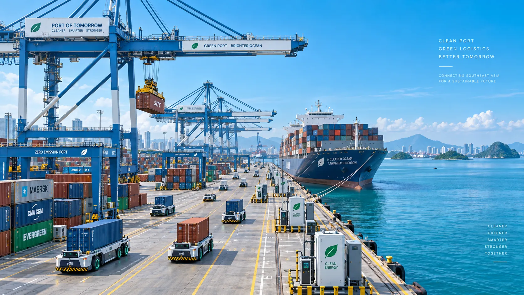
Smart Port Systems in Southeast Asia: Investment Priorities and Adoption Barriers
Smart port systems Southeast Asia: discover investment priorities, adoption barriers, and practical steps to build resilient, connected, high-performing terminals.

How to Evaluate Terminal Efficiency Solution Suppliers for High-Throughput Operations
Choose a terminal efficiency solutions supplier with confidence. Explore proven criteria for throughput, integration, lifecycle cost, safety, and reliable delivery.
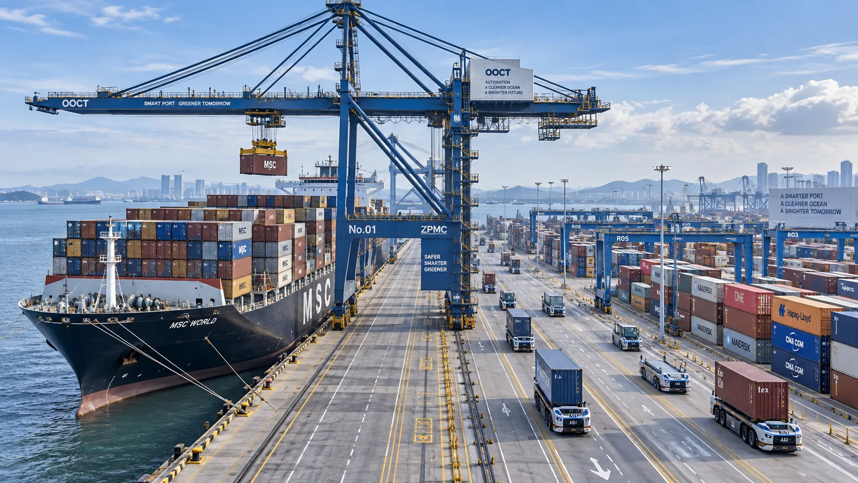
How to Specify a Quay Crane for Container Terminals by Vessel Size and Throughput?
Quay crane for container terminals: learn how to match outreach, lift height, capacity, automation, and cycle performance to vessel size and throughput goals.
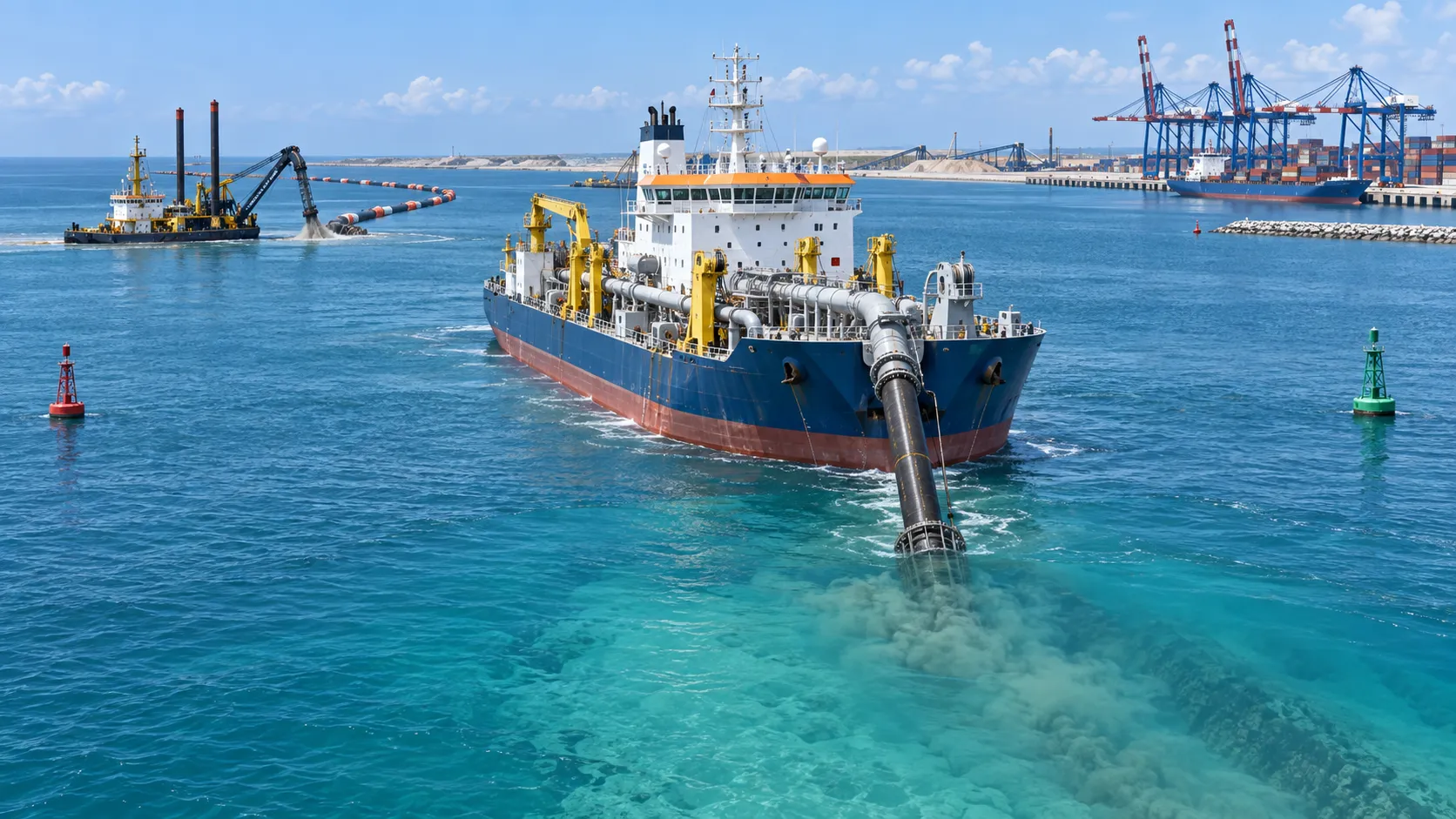
What Dredging Equipment Is Needed for Channel Deepening?
What dredging equipment is needed for channel deepening? Explore dredgers, pipelines, survey tools, and planning strategies for safer, more efficient port access.
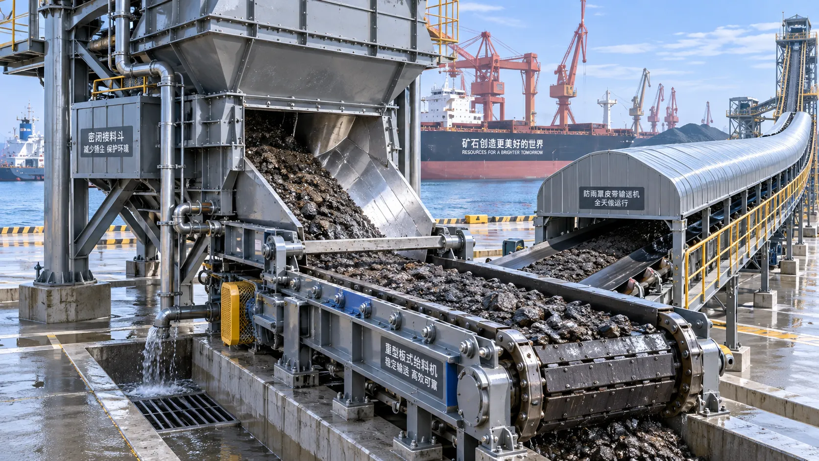
Which Bulk Handling Equipment Suits High-Moisture Cargo?
Which bulk handling equipment suits high-moisture cargo? Compare belt, apron, screw, drag, and slurry systems for reliable flow, less carryback, and higher terminal uptime.
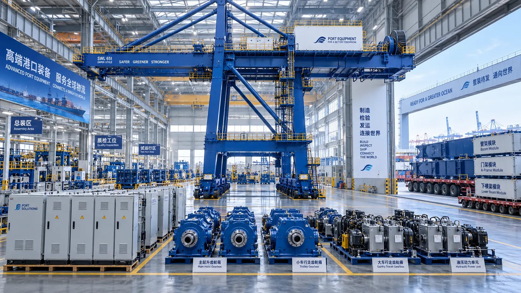
How Can Port Equipment Lead-Time Risk Be Managed?
How can port equipment lead-time risk be managed? Explore practical strategies to control critical paths, suppliers, transport, site readiness, and commissioning delays.
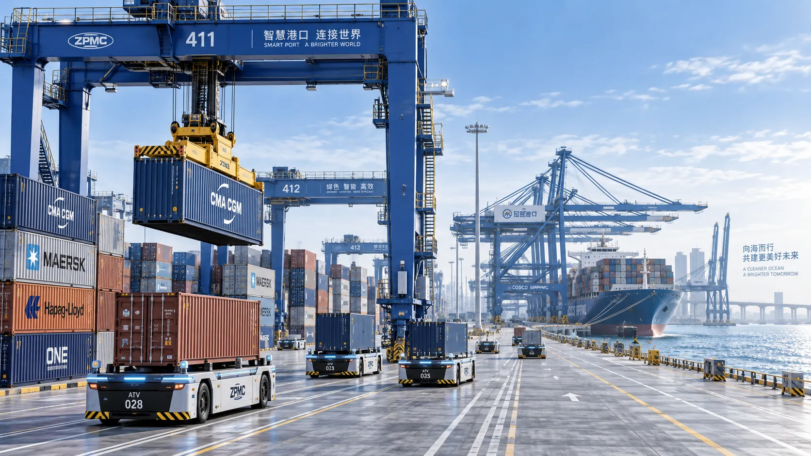
Terminal Automation Technologies That Raise Container Throughput Without Yard Disruption
Terminal automation technology that increases container throughput without disrupting yard flow. Explore smarter integration, resilient workflows, and phased deployment strategies.
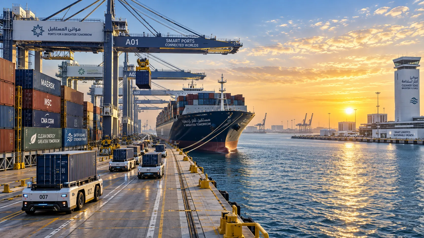
Middle East Port Automation: Key Market Drivers, Projects, and Investment Risks
Port automation systems Middle East: explore market drivers, flagship projects, integration challenges, and investment risks shaping smarter, resilient terminals.
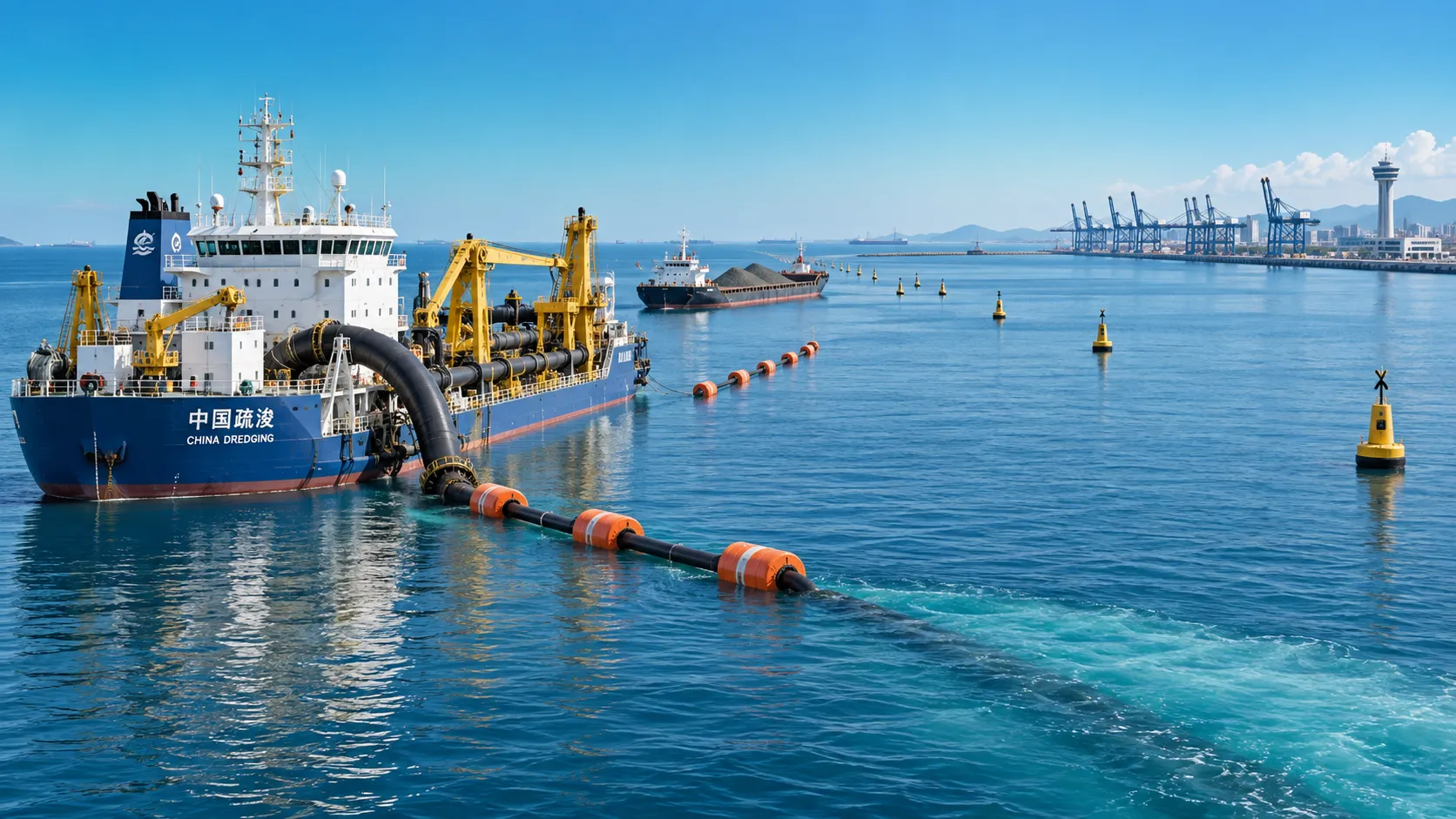
Planning Offshore Dredging Operations: Key Risks, Methods, and Project Controls
Offshore dredging operations demand smart planning. Explore key risks, proven methods, environmental controls, and project strategies for reliable delivery.