Related News
- 00
0000-00
Marine Engineering Solutions for Dredging in Ports: Key Design Factors - 00
0000-00
What Data Does a Smart Port Control Architecture Need to Operate? - 00
0000-00
CE-Marked Quay Cranes: How to Verify Compliance Documents - 00
0000-00
Port Automation Systems in Latin America: Choosing the Right Solution - 00
0000-00
Scalable Automated Port Systems: Planning for Terminal Capacity Growth
0000-00
Selecting Quay Crane Systems: Matching Outreach and Lifting Capacity to Vessel Size
A quay crane is compatible with a vessel only when it can reach every required container position, clear the highest planned deck stack, and lift the intended load configuration throughout the working envelope. Vessel capacity in TEU is not a sufficient selection basis: ships with similar nominal capacity can have different beams, container-row arrangements, deck-stack heights, and operating drafts.
Selecting quay crane systems for marine cargo therefore starts with a vessel-and-berth geometry assessment, not a comparison of headline lifting capacities. Outreach, hoisting range, and safe working load must be specified together. A crane that satisfies each requirement separately may still fail if its maximum load is unavailable at the required outreach or its lifting height leaves insufficient clearance for the planned container path.
Define the vessel envelope before choosing a crane size
The design basis should distinguish vessels that must be handled routinely from vessels accepted under operating restrictions. This prevents an occasional large call from silently becoming the specification for every crane, while also avoiding equipment that cannot support the terminal’s committed service profile.
For each representative vessel, obtain general arrangement information and container stowage geometry rather than relying solely on length overall, beam, or a commercial vessel class. The relevant information includes:
- Transverse positions of the outermost container-row centers relative to the vessel centerline.
- Maximum planned deck-stack elevations under the lightest relevant operating condition.
- Lowest container pickup positions in the holds under the deepest relevant operating condition.
- Hatch-cover dimensions, handling weights, and designated lifting arrangements.
- Restrictions created by lashing bridges, deck fittings, superstructure, or other obstructions.
The berth contributes another set of dimensions: waterside rail position, fender geometry, quay elevation, operating water levels, rail gauge, and permissible vessel movement. These should share a common coordinate system. Combining a vessel dimension measured from the centerline with a crane dimension measured from the quay edge is an avoidable source of specification error.
Future vessel allowance should be explicit. Identify the additional row coverage, stack elevation, or load configuration being reserved, rather than requesting a vaguely “future-proof” crane. Each allowance affects structural demand, machinery sizing, or both.
Translate container-row positions into required outreach
Outreach is commonly referenced from the waterside rail centerline to the lifting centerline at its maximum waterside position, but the supplier’s definition must be confirmed. Boom length, distance beyond the quay edge, and usable lifting outreach are not interchangeable measurements.
For a vessel berthed alongside, a practical geometric expression is:
Required outreach = waterside rail setback from the quay reference + distance from that reference to the near-side hull + distance from the near-side hull to the farthest required container centerline + operating allowance.
The second term must reflect the applicable fender condition and berth geometry. The final allowance should address defined positional variation and movement within the operating limits, rather than serving as an unexplained contingency.
Consider an illustrative berth where the waterside rail is 4.0 m behind the quay face, the near-side hull is 1.5 m beyond that face, and the farthest required container centerline is 57.0 m from the near-side hull reference. The geometric reach is 62.5 m before any operating allowance. A crane advertised with 62 m outreach would not satisfy that geometry, even if its stated row coverage appeared suitable.
Row count remains useful for initial screening, but it cannot replace coordinates. The transverse span depends on row-center spacing, hull-to-container offsets, and the particular stowage arrangement. Multiplying the number of rows by nominal container width does not establish an accurate outreach requirement.
Reach should also be checked against permissible list and the actual height of the target position. A listed vessel changes the horizontal and vertical coordinates of elevated deck containers. The appropriate check is a vessel cross-section against the crane’s working envelope, not simply a beam measurement with a percentage added.
Check lifting height and hold depth from the same datum
Above-rail lifting height must accommodate the highest required lifting position and the clearance needed to transfer the container safely. Reaching a container’s top corner castings is not the same as being able to move that container over an adjacent stack.
The specification should state whether the quoted height refers to the spreader’s twistlock plane, another spreader reference, or the hook. It should then define the required lift path, including spreader dimensions, container height, clearance above obstructions, and any headroom consumed by special lifting attachments.
Maximum deck-stack elevation relative to the crane rail is governed by water level, vessel draft, trim or list, and the planned stack arrangement. High operating water combined with a lightly loaded vessel can govern the upper lifting requirement. The combination must be operationally credible; unrelated extreme values should not be added without checking whether they can occur together.
Below-rail lowering depth requires a separate check. Low operating water and a deeper vessel condition can move hold pickup points farther below the rail datum. Adequate upper lifting height does not establish that the crane has enough rope travel to reach the lowest required container.
Obstructions also shape the usable path. Lashing bridges, hatch coamings, and high adjacent stacks can force additional vertical movement before trolley travel begins. A nominally sufficient hoisting range can therefore produce either an inaccessible position or a slower cycle if the clearance geometry is poorly matched.
Specify what the lifting capacity actually includes
A capacity figure is incomplete unless it identifies the lifting arrangement and the load reference. Capacity under the spreader, capacity under the headblock, and capacity under a cargo hook can describe different permissible loads. Bid comparisons must place these values on the same basis.
Where capacity is stated as net load under the spreader, the crane design must still account for the spreader and other suspended equipment. Where a gross suspended-load rating is quoted, attachment weight reduces the payload available. The supplier should document the load accounting for each proposed operating mode.
For example, a 65 t net twin-lift rating does not permit two 35 t containers: their combined mass is 70 t. Even where the combined mass is within the rating, individual container limits or permitted load imbalance may prevent the lift. A total-weight check alone is insufficient.
Hatch covers deserve their own load case. Their mass, lifting-point arrangement, dimensions, and wind exposure differ from those of containers. A higher hook rating may be available for this duty, but it should not be treated as an equivalent container-handling rating.
Require capacity at the positions where it will be used
Maximum outreach and maximum lifting capacity should not be accepted as independent guarantees. The supplier must confirm the permissible load across the required trolley travel and lifting range, including any restrictions on speed or motion combinations.
A useful requirement is a guaranteed operating envelope covering the outermost row, the highest transfer position, the deepest hold position, and the landside transfer points. For each governing case, specify the load configuration and required operating mode. This exposes restrictions that a single nameplate capacity cannot show.
Structural verification must include applicable dynamic effects, accelerations, braking, skew loading, and wind conditions. These belong in the agreed design basis; they should not be replaced by an arbitrary extra payload margin. Increasing the nominal lifting rating does not automatically resolve fatigue duty or structural-response requirements.
Fatigue assessment should reflect the expected load spectrum and number of operating cycles. Two cranes with the same maximum safe working load can have different suitability for sustained heavy-container work. The specification should connect service life assumptions to credible lift distributions, operating hours, and duty classifications under the applicable design framework.
Test whether the larger crane fits the berth
Additional outreach and capacity can increase crane self-weight, overturning demand, and wheel loads. An existing berth therefore needs a structural assessment based on the proposed crane reactions, not an assumption that a similar rail gauge establishes compatibility.
Request wheel-load information for the governing operating and non-operating cases, including load distribution, wheel spacing, storm restraint, and uplift where relevant. Rail beams, foundations, quay structures, tie-downs, and buffers must be assessed against those reactions. More wheels may redistribute loads, but they do not eliminate the need to verify the supporting structure.
Physical fit extends beyond the waterside working envelope. The raised boom must clear relevant vessel structures, while any airspace restrictions may limit overall crane height. Landside backreach must serve the intended transfer lanes without conflicting with buildings, traffic routes, or adjacent equipment. Crane-to-crane spacing and interference can also restrict how many cranes work a vessel simultaneously.
These interfaces determine whether extra vessel coverage is usable. A longer-reaching crane that forces an unfavorable berth arrangement or exceeds the quay’s allowable reactions is not a direct equipment substitution.
Use representative vessel cycles to compare compliant options
Once geometric and load requirements are satisfied, compare performance using representative container moves. Maximum trolley speed alone is a weak indicator of productivity: longer travel, acceleration distance, hoisting clearance, positioning time, and landside handover all influence the cycle.
The comparison should include far-side deck lifts, deep-hold lifts, heavy single lifts, and twin lifts where planned. Require the supplier to state whether quoted hoisting speeds apply at full load or reduced load, and whether simultaneous motions are permitted under the evaluated conditions.
Twin-lift capability should be evaluated against the intended stowage and landside handling arrangement. It adds value only where containers can be paired within the approved weight and geometry limits and received without creating a transfer bottleneck. A higher combined rating cannot guarantee more productive lifts.
The final acceptance basis should combine drawing review, structural and machinery verification, and agreed testing. Acceptance criteria need to demonstrate reach, lifting range, rated-load operation, relevant motion performance, and protective functions at the specified conditions. Any reliance on simulation or calculation for conditions not reproduced during testing should be defined contractually.
The strongest selection is not the crane with the largest advertised outreach or lifting capacity. It is the crane with a verified working envelope that covers the committed vessel fleet, supports the intended lifting modes, and remains compatible with the berth. Reserve capacity is justified when it corresponds to an identified vessel or operating requirement; otherwise, it can add structural burden without removing a meaningful handling constraint.
Related News
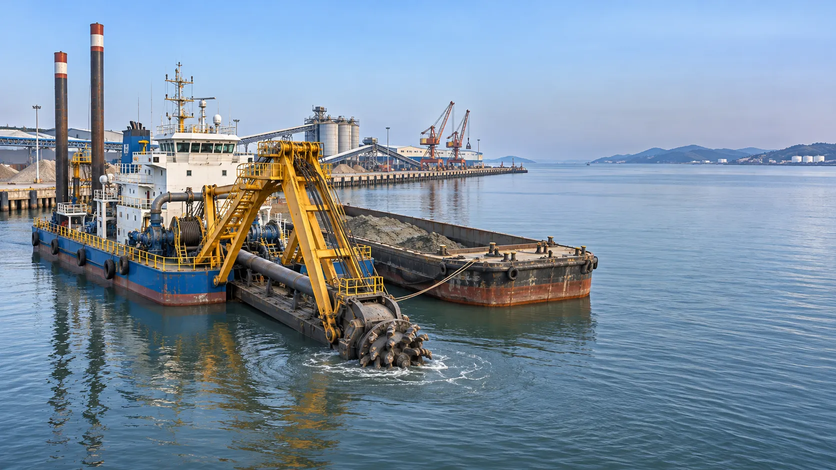
Marine Engineering Solutions for Dredging in Ports: Key Design Factors
Explore marine engineering solutions for dredging ports, from equipment selection and sediment management to safe navigation and survey verification.
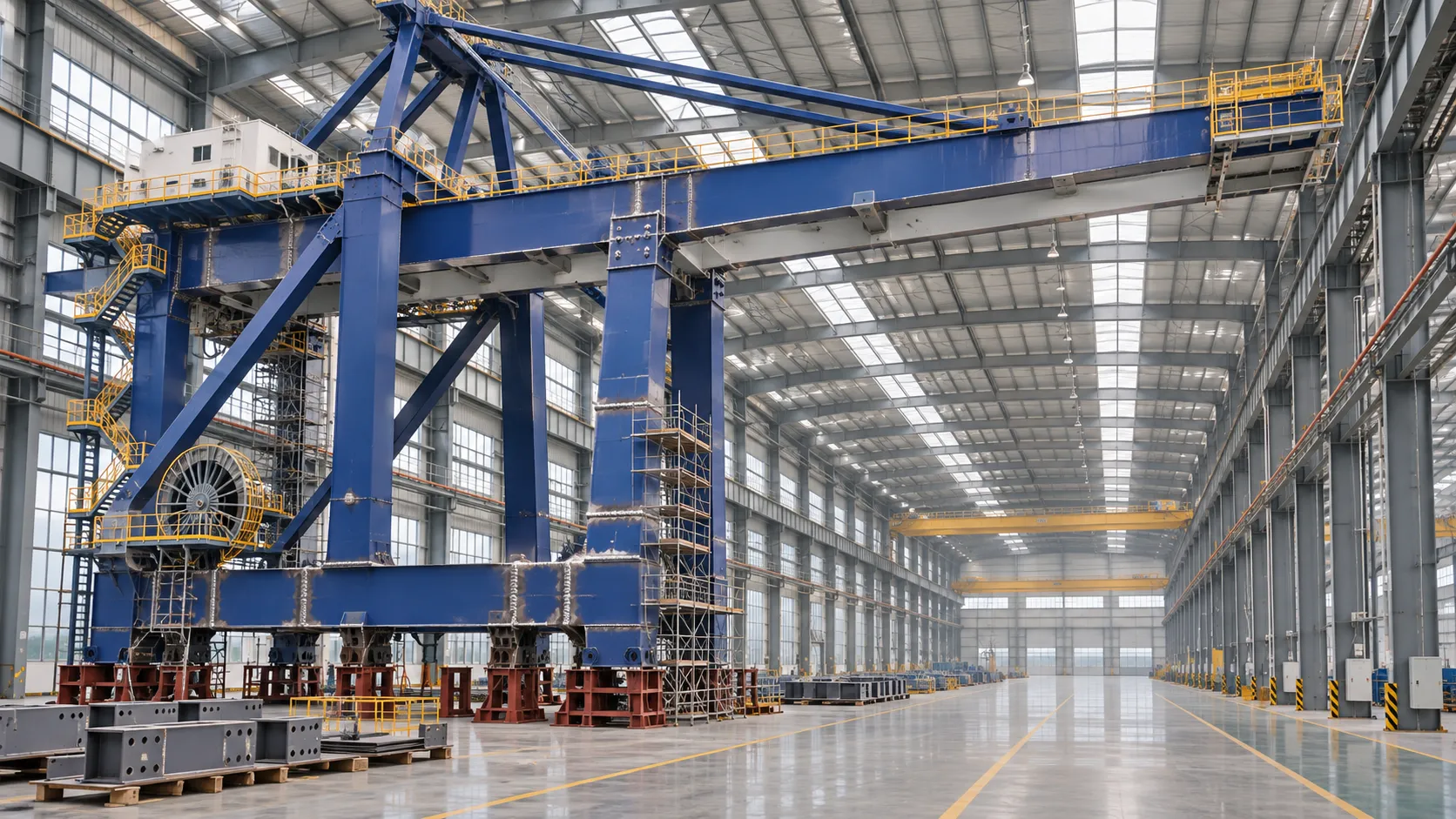
How to Evaluate a Quay Crane Factory: Capacity, Quality and Delivery
Evaluate a quay crane factory with confidence. Learn how to verify production capacity, quality controls, delivery plans, and lifecycle costs before you commit.
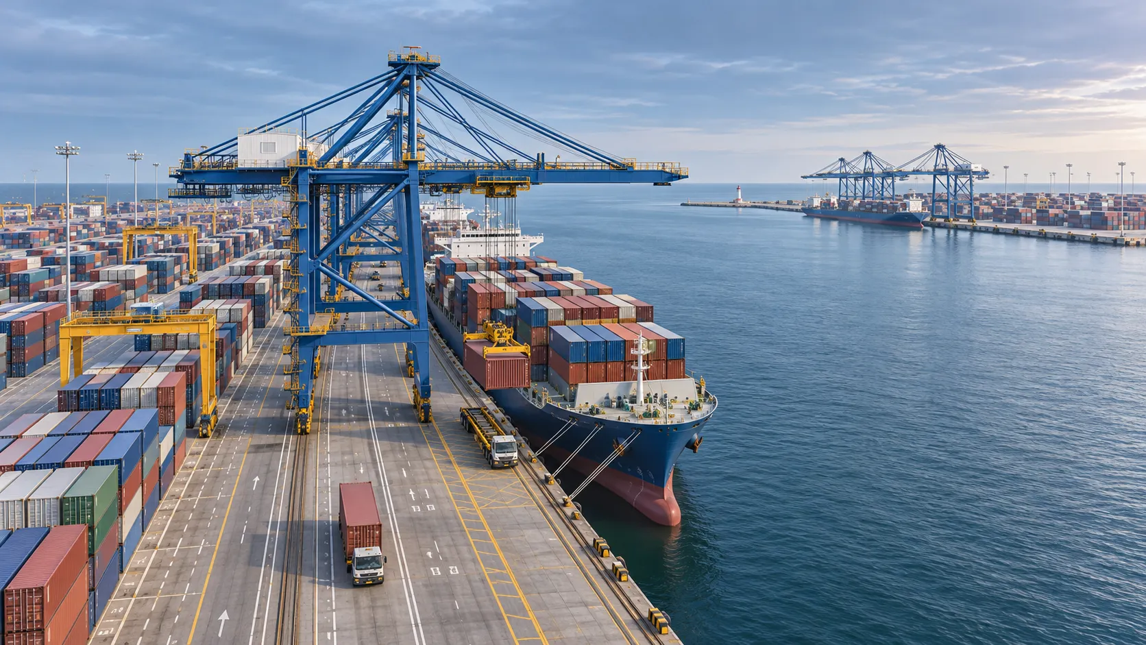
What Data Does a Smart Port Control Architecture Need to Operate?
What data is needed for a smart port control architecture? Discover the essential operational feeds, integration requirements and safety checks.
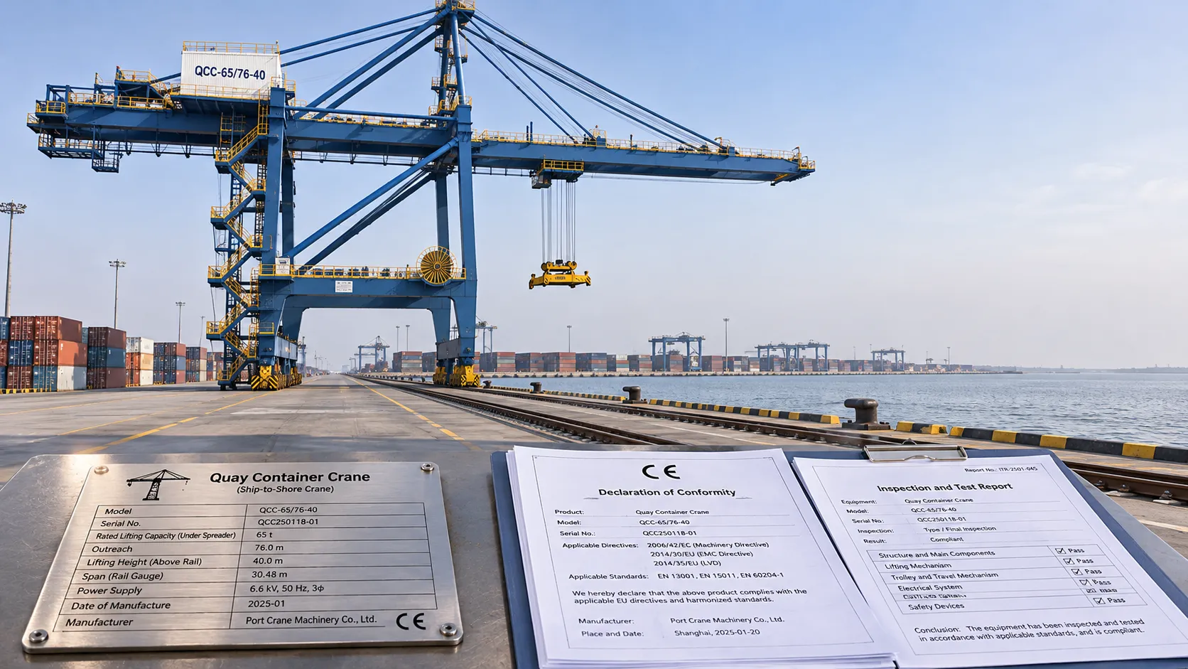
CE-Marked Quay Cranes: How to Verify Compliance Documents
Quay crane CE certified? Learn how to verify declarations, risk assessments and test records for the complete machine before acceptance.
Port Automation Systems in Latin America: Choosing the Right Solution
Explore port automation systems Latin America terminals can use to reduce congestion, assess integration risks, and choose the right solution with confidence.

Scalable Automated Port Systems: Planning for Terminal Capacity Growth
Discover how scalable automated port systems support phased terminal growth, reduce bottlenecks and guide smarter capacity investments.
Europe's Coastal Economies: Key Industries, Jobs and Climate Risks
Explore coastal economics in Europe: discover key industries and jobs, the climate risks they face, and how coastal communities can adapt.

Bulk Cargo Handling Equipment for Ports: Choosing by Cargo and Capacity
Choose bulk cargo handling equipment for ports with confidence. Compare cargo types, realistic throughput, equipment options, and lifecycle costs.
What Affects Container Terminal Efficiency in Southeast Asia?
Discover what affects terminal efficiency in Southeast Asia, from berth planning and yard congestion to inland access, and learn how to assess performance.