Related News
- 00
0000-00
Marine Engineering Solutions for Dredging in Ports: Key Design Factors - 00
0000-00
What Data Does a Smart Port Control Architecture Need to Operate? - 00
0000-00
CE-Marked Quay Cranes: How to Verify Compliance Documents - 00
0000-00
Port Automation Systems in Latin America: Choosing the Right Solution - 00
0000-00
Scalable Automated Port Systems: Planning for Terminal Capacity Growth
0000-00
Marine Engineering Solutions for Dredging in Ports: Key Design Factors
Effective marine engineering solutions for dredging begin with a design that connects the required navigable depth to the material in the seabed, the equipment available, and the destination of the excavated sediment. A dredger that performs well in an open approach channel may be unsuitable beside an operating berth, where restricted maneuvering space, buried utilities, and tighter excavation tolerances control the work.
The design should establish a defensible excavation boundary, identify the conditions that could change production, and define how the finished seabed will be verified. These decisions influence the construction sequence as much as the choice of vessel.
Set the Dredging Envelope Before Estimating Volume
Start with the operational requirement: the vessels expected to use the channel or berth, their drafts and maneuvering characteristics, and the water levels under which access must be maintained. The required seabed level follows from an under-keel clearance assessment that accounts for vessel motions, squat, water-level uncertainty, and the applicable navigation criteria. A single depth applied across an entire port can produce unnecessary excavation in one area while leaving a constraint in another.
Channel bends, turning basins, berth pockets, and transitions to existing depths require separate attention. A vessel needs more than vertical clearance; it also needs sufficient width and room to maneuver. Where traffic patterns constrain the design, a navigation assessment can test whether the proposed geometry accommodates the vessels and operating conditions assumed.
Once the required surface is established, distinguish among several depth lines. The design depth is the target navigational surface; an allowable overdepth, where specified, recognizes excavation tolerances; and an advance maintenance allowance may be considered where sedimentation is expected before the next campaign. These allowances serve different purposes. Combining them without explanation obscures both the payable quantity and the reason for removing material below the navigational requirement.
Volume calculations also need side slopes, transition areas, and the limits of existing structures. A steep slope that reduces the calculated quantity may be unstable in soft sediment. Conversely, a conservative slope extending into a berth foundation or neighboring channel is not a workable design. Ground conditions and structural interfaces must establish the feasible envelope before the quantity is treated as a firm basis for scheduling.
Characterize the Ground in Layers, Not as an Average
Bathymetry shows the shape of the seabed, but it does not establish what lies beneath it. Combine a current hydrographic survey with geotechnical sampling and, where appropriate, geophysical investigation. Position boreholes and sampling locations to resolve changes in material along the excavation route and through the full proposed cut, including potential overdepth and slope zones.
Soft silt over dense sand creates a different production profile from a uniform deposit of either material. The upper layer may be removed quickly, while the lower layer governs cutter power, pump wear, excavation cycle time, and achievable slope. Thin hard layers, debris, boulders, or remnants of former structures can interrupt production even when the average material description looks favorable.
For cohesive soils, strength and consistency affect whether a draghead, cutter, or bucket can excavate the material efficiently. For granular soils, particle size and density influence excavation resistance and pipeline transport. Rock requires assessment of its strength, fracture pattern, and removability; its presence does not automatically establish that blasting is necessary or permitted.
Sampling must also support sediment management. Material that appears physically similar can have different contaminant concentrations at different depths or locations. If the proposed receiving site has acceptance criteria, define sampling and analytical methods early enough to separate material streams before excavation. A design based on one composite characterization can fail when a localized layer requires different handling.
Match the Dredging Method to the Whole Material Path
Equipment selection should cover excavation, transport, and placement as one system. High excavation capacity has limited value if hopper space, pumping distance, barge availability, or the receiving site restricts the flow of material.
- Trailing suction hopper dredgers are suited to many open-water channel works where there is room to maneuver and material can be carried to a suitable placement area. Close work beside structures and highly variable hard material can limit their effectiveness.
- Cutter suction dredgers excavate while positioned and can pump material through a pipeline. They are useful for controlled cuts and some stronger soils, but anchors, spuds, pipelines, and swing movements must fit around navigation and existing infrastructure.
- Backhoe or grab dredgers offer controlled mechanical excavation near confined features and can handle certain debris or mixed ground. Their output depends on the excavation cycle and on reliable barge or other transport capacity.
The distinction between production and productivity matters. A nominal pump capacity or bucket size does not account for repositioning, sailing, discharge, equipment maintenance, traffic restrictions, or the time needed to deal with isolated obstructions. Build the schedule from the complete operating cycle and use separate assumptions for materially different work zones.
For hydraulic transport, assess the pipeline route, elevation changes, sediment characteristics, mixture concentration, and available pumping pressure together. A longer line or a coarser mixture can increase transport resistance; adding water may ease pumping while increasing the volume that must be managed at the receiving area. Booster requirements and discharge arrangements should therefore be assessed alongside the dredger, not added after the placement plan is fixed.
Mechanical excavation creates a different interface: the receiving barge must be available when needed, have an appropriate route to the placement area, and comply with the material-handling requirements. A berth pocket with short digging cycles can still experience low effective output if barges wait for traffic windows or the placement site cannot accept loads at the planned rate.
Protect Structures and Maintain Port Access
Existing quays, piles, revetments, intake structures, cables, and pipelines can determine the dredging boundary. Gather available as-built information, then reconcile it with survey and utility-detection results. The absence of a feature on a drawing is not proof that the seabed is clear, particularly in an area with a long construction history.
Excavation near a quay can remove soil that contributes to foundation or retaining-wall stability. The permissible toe position and side slope must be evaluated against the structural design and ground conditions. Where the required navigation depth conflicts with those limits, the solution may involve staged excavation, structural assessment or modification, or a revised operational geometry. Simply specifying greater digging accuracy does not resolve an unstable slope.
Port traffic creates a separate spatial constraint. Define work zones, transit routes, and the conditions for temporarily moving equipment. A cutter dredger's anchor pattern or floating pipeline may occupy substantially more space than its hull; a hopper dredger needs room to turn and load. These footprints should appear on the same operational drawings as vessel movements and emergency access routes.
Sequence the work so that partially completed cuts do not create unexpected shoals or narrow passages. At an active berth, a short working window can favor precise, localized excavation, but repeated mobilization and interruptions must be included in the programme. Agree on communication and handover arrangements for each change in the navigable area.
Design Sediment Placement Alongside Excavation
The placement route must be viable for the expected sediment volume, properties, and rate of delivery. Potential destinations include an approved marine placement area, a confined facility, or a beneficial-use project where the material and receiving design are compatible. Each option introduces different transport, containment, water-management, and monitoring requirements.
For a confined receiving area, storage is not determined by the excavated in-situ volume alone. Dredged sediment can contain substantial water, and its volume and behavior change during transport, placement, and consolidation. Settlement time, available containment capacity, decant arrangements, and the strength needed for any later construction affect whether the facility can accept material at the planned production rate.
Where contaminated sediment is present, define excavation boundaries and handling controls around the characterization results and the requirements applicable to the selected destination. Overly broad removal can create avoidable disposal demand; boundaries drawn too tightly around sparse samples can leave unsuitable material behind or mix it with cleaner sediment. A provision for additional delineation and segregated handling is often more useful than assuming the initial boundary is exact.
Control Turbidity Without Ignoring Its Cause
Sediment can be released at the excavation point, during overflow or transfer, and at the placement site. The dominant source varies with equipment and operating method. Monitoring only the dredger may miss a problem at discharge, while a visible surface plume alone does not establish the concentration throughout the water column or its effect on a sensitive receptor.
Environmental controls should follow the permit conditions and the location of sensitive habitats, intakes, and other receptors. Possible measures include modifying excavation methods, restricting overflow where applicable, adjusting the work sequence, or using containment where local currents, water depth, and vessel movements make it practical. A barrier that interferes with navigation or cannot be maintained under local conditions may provide less control than a change in the dredging operation.
Define monitoring locations, baseline conditions, measurement methods, and response actions before work starts. A response procedure should distinguish a suspected dredging-related change from background variation, while still allowing work to be adjusted promptly when the agreed trigger is reached.
Make Survey and Acceptance Rules Part of the Design
Pre-dredge, progress, and final surveys must use compatible horizontal and vertical reference systems. Tidal corrections, positioning, sound-speed treatment, survey coverage, and data processing affect whether two surfaces can be compared reliably. A depth discrepancy is not necessarily an excavation failure if the surveys used different datums or corrections.
Specify how high spots, isolated obstructions, slopes, and areas close to structures will be assessed. Full coverage may require different survey methods in shallow water or around piles, where a single system can leave gaps. The acceptance process should state how uncertain or inaccessible areas are resolved and which party confirms that the navigable surface meets the agreed criteria.
Progress surveys also support early correction. Repeated high spots may indicate inaccurate positioning, an unsuitable excavation sequence, or hard material that was not represented in the ground model. Each calls for a different response; simply repeating the same pass can consume time without removing the underlying constraint.
Allow the Construction Plan to Respond to Ground Conditions
Before mobilization, identify the assumptions that control the programme: material layers, expected obstructions, working hours, traffic windows, placement availability, and equipment production by zone. Record what evidence would require those assumptions to be revised. This creates a practical basis for discussing changed conditions without treating every variation as an isolated surprise.
During excavation, compare production records with survey results and the observed material. A sudden fall in output might reflect stronger soil, a blocked pipeline, increased pumping distance, or interruptions from vessel traffic. Separating these causes matters because they lead to different actions, from equipment maintenance to a revised excavation sequence or further investigation.
Closeout should leave a usable record of the final surveyed surface, any accepted departures, remaining obstructions, and the sediment placement history. That record becomes the starting point for maintaining the channel and assessing future changes at the berth.
Related News
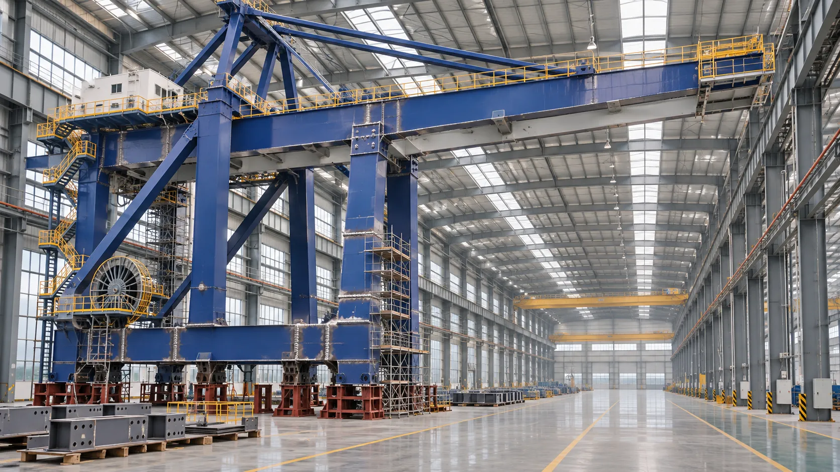
How to Evaluate a Quay Crane Factory: Capacity, Quality and Delivery
Evaluate a quay crane factory with confidence. Learn how to verify production capacity, quality controls, delivery plans, and lifecycle costs before you commit.
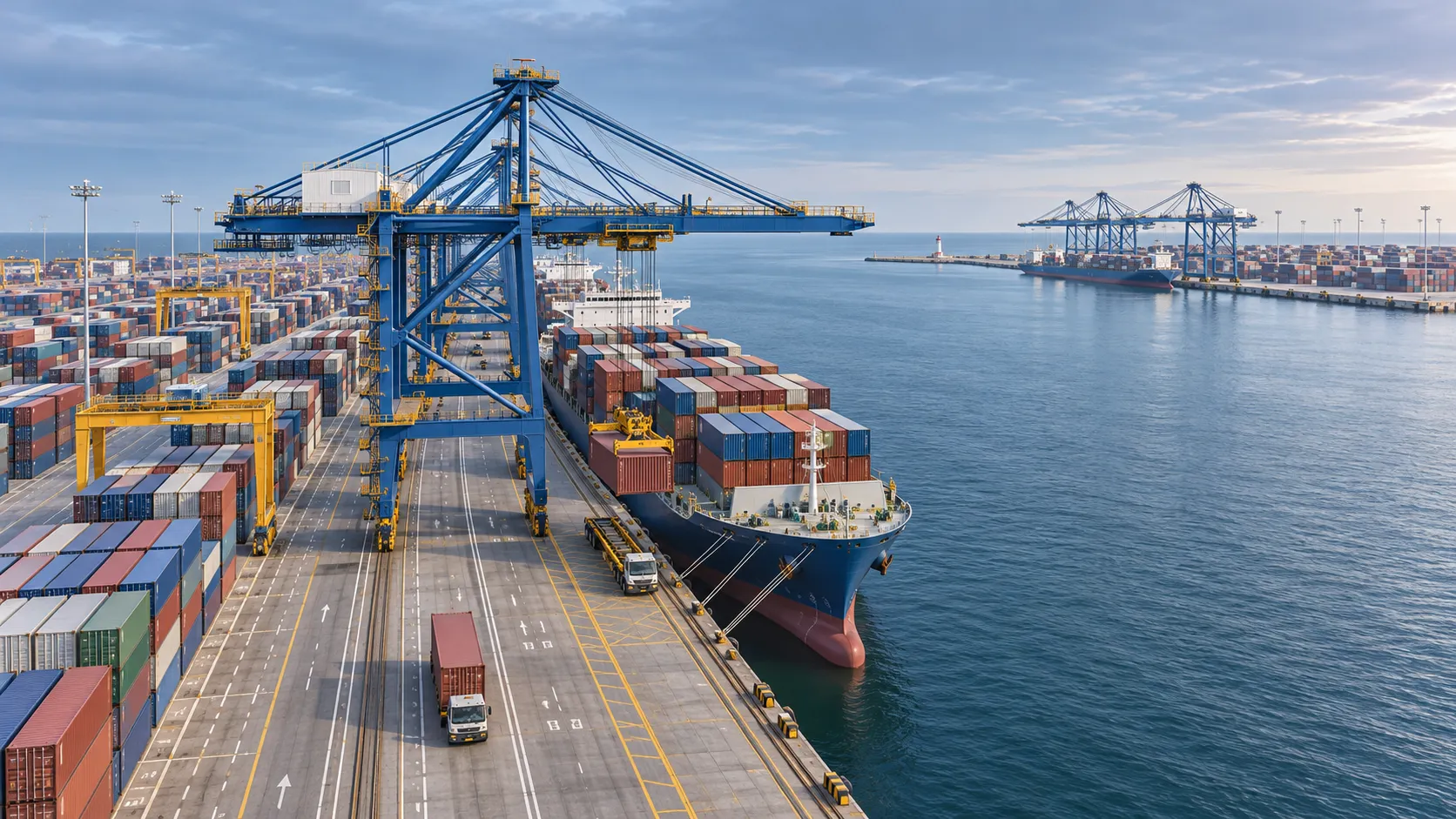
What Data Does a Smart Port Control Architecture Need to Operate?
What data is needed for a smart port control architecture? Discover the essential operational feeds, integration requirements and safety checks.
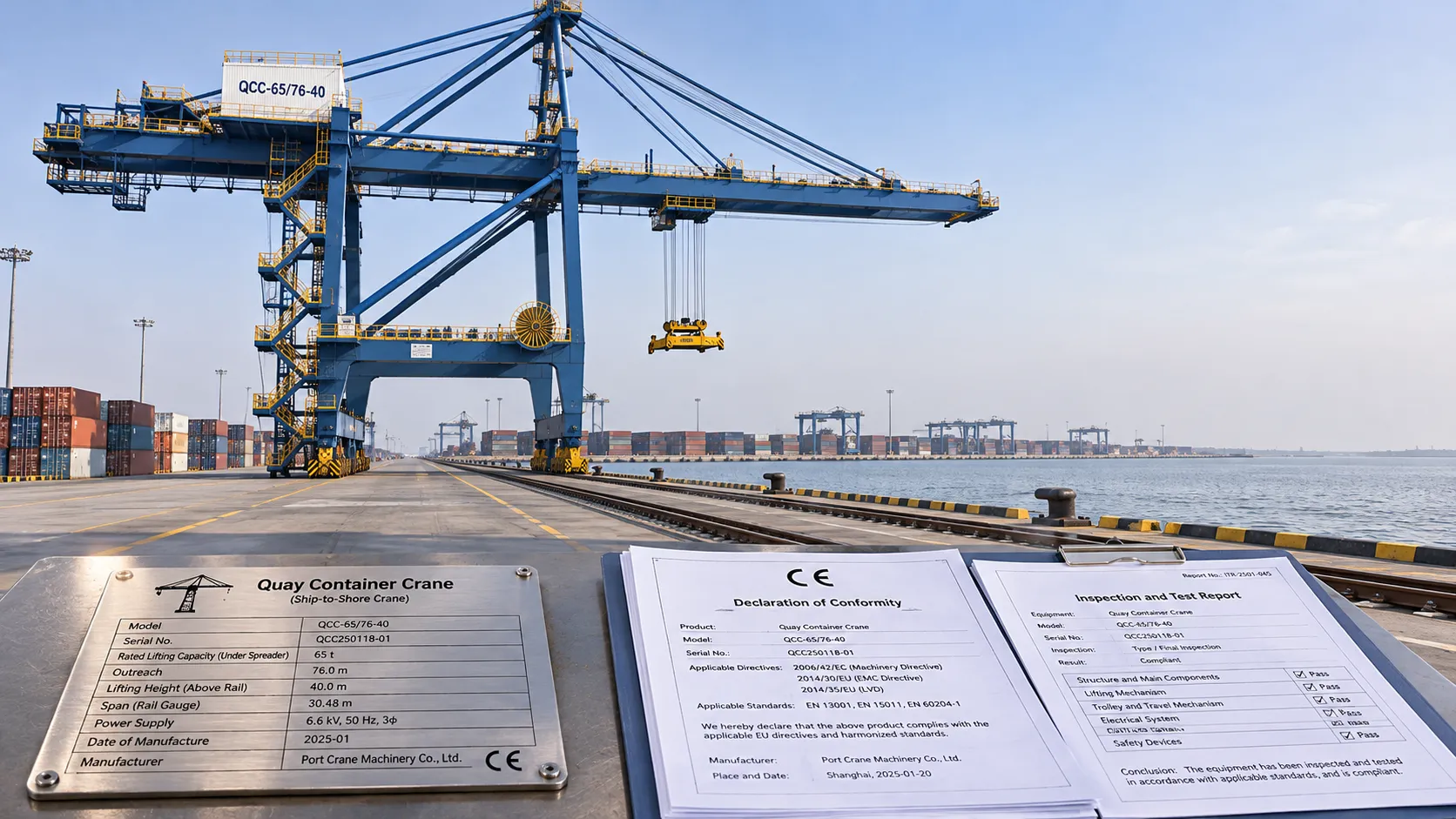
CE-Marked Quay Cranes: How to Verify Compliance Documents
Quay crane CE certified? Learn how to verify declarations, risk assessments and test records for the complete machine before acceptance.
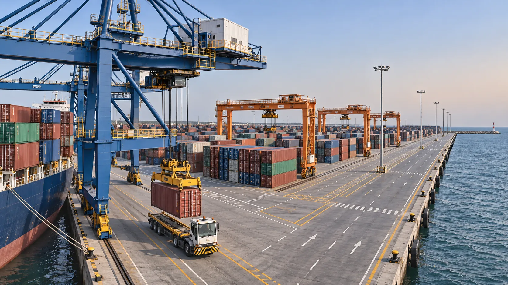
Port Automation Systems in Latin America: Choosing the Right Solution
Explore port automation systems Latin America terminals can use to reduce congestion, assess integration risks, and choose the right solution with confidence.

Scalable Automated Port Systems: Planning for Terminal Capacity Growth
Discover how scalable automated port systems support phased terminal growth, reduce bottlenecks and guide smarter capacity investments.
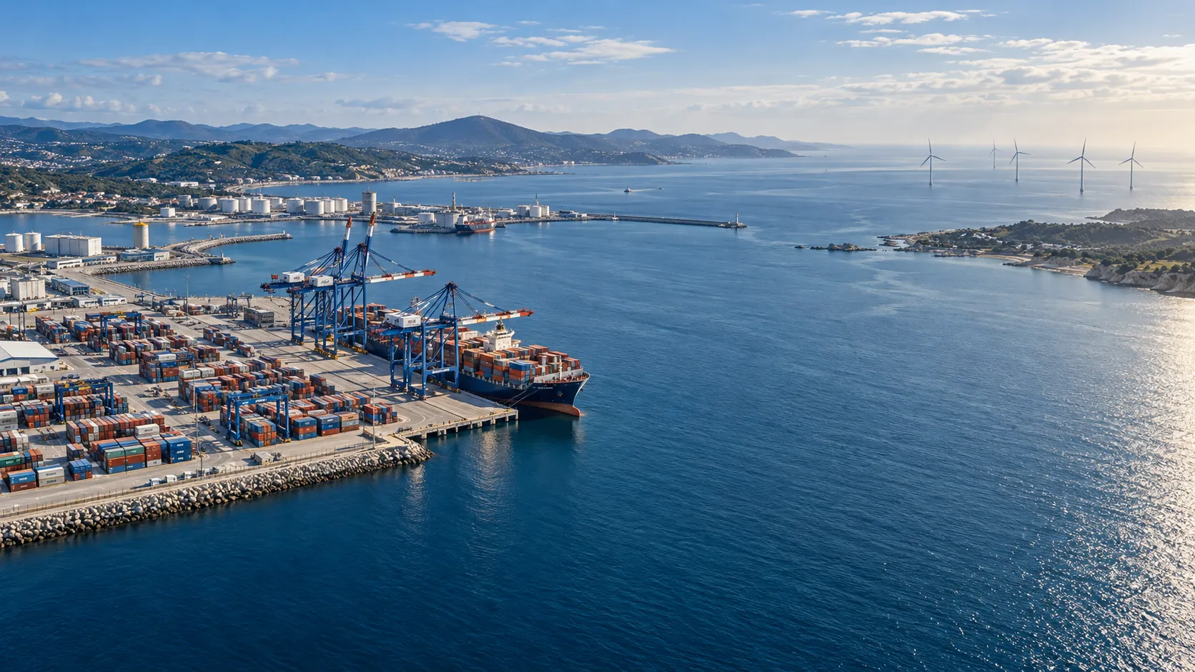
Europe's Coastal Economies: Key Industries, Jobs and Climate Risks
Explore coastal economics in Europe: discover key industries and jobs, the climate risks they face, and how coastal communities can adapt.
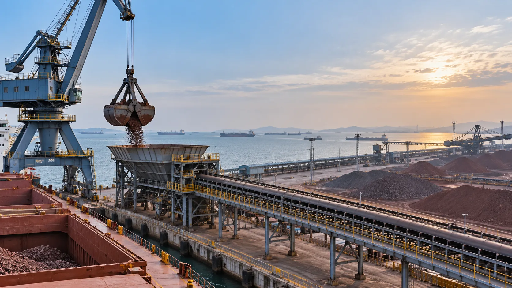
Bulk Cargo Handling Equipment for Ports: Choosing by Cargo and Capacity
Choose bulk cargo handling equipment for ports with confidence. Compare cargo types, realistic throughput, equipment options, and lifecycle costs.
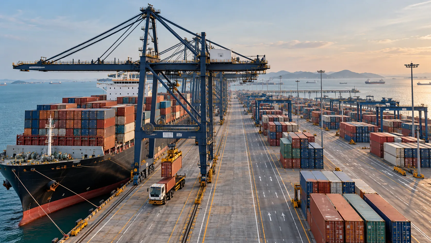
What Affects Container Terminal Efficiency in Southeast Asia?
Discover what affects terminal efficiency in Southeast Asia, from berth planning and yard congestion to inland access, and learn how to assess performance.

Choosing Path Planning Systems for Outdoor Robots in the Middle East
Compare path planning systems Middle East operators need for outdoor robots. Explore heat, dust, safety, and fleet integration criteria to choose with confidence.