Related News
- 00
0000-00
How to Specify a Quay Crane for Container Terminals by Vessel Size and Throughput? - 00
0000-00
Which Bulk Handling Equipment Suits High-Moisture Cargo? - 00
0000-00
Terminal Automation Technologies That Raise Container Throughput Without Yard Disruption - 00
0000-00
Planning Offshore Dredging Operations: Key Risks, Methods, and Project Controls - 00
0000-00
Where Do Automated Guided Vehicles Deliver the Fastest Warehouse Gains in the Middle East?
Selecting Heavy Terminal Gear Systems for High-Torque, Continuous-Duty Operations
A terminal crane, ship unloader, stacker-reclaimer, or heavy transfer machine can meet its rated capacity on a datasheet and still be the wrong choice for a high-torque, continuous-duty application. The failure usually becomes visible after commissioning: hoist motors run hot during repetitive cycles, gearboxes develop vibration, drives derate under sustained load, or maintenance teams cannot reach critical components without stopping adjacent operations.
For this duty profile, the right selection is not the system with the largest nominal rating. It is the system whose drivetrain, thermal design, controls, structural interfaces, and maintenance arrangement are matched to the actual load spectrum and operating pattern. When selecting heavy terminal gear systems, begin with the most demanding repeated operating condition—not the average container, average cargo flow, or peak load in isolation.
Start with the duty cycle, not the headline capacity
Rated lifting capacity and installed motor power are necessary reference points, but neither defines whether equipment can sustain torque over long working periods. A terminal machine may experience relatively few maximum-load lifts while spending most of its time accelerating, decelerating, traversing, slewing, grabbing, or holding load against wind and grade resistance. Each of those actions creates a different torque demand on motors, couplings, brakes, gears, and bearings.
Before comparing equipment configurations, turn the intended operation into a load profile. This should identify:
- Load magnitude by operating condition, including empty tool weight, nominal working load, overload allowances, and dynamic effects.
- Cycle phases such as pickup, acceleration, constant-speed travel, deceleration, positioning, holding, and discharge.
- Expected cycles per hour and the duration of active motion versus idle time.
- Changes in duty caused by vessel turnaround peaks, shift handovers, weather delays, or material-flow interruptions.
- Travel resistance from rails, tires, gradients, alignment conditions, and surface contamination.
- Torque reversals, frequent plugging, regenerative braking, or repeated inching during precise positioning.
A continuous-duty application should be assessed using root-mean-square torque and thermal loading across the operating cycle. Peak torque determines whether the drivetrain can survive the highest transient demand; equivalent torque and motor heating determine whether it can perform repeatedly without derating. Selecting solely for peak output can produce an oversized but inefficient system. Selecting solely for average output may create a machine that appears adequate until it faces sustained peak throughput.
Separate high torque from high power
High power and high torque are related but not interchangeable. Power is a product of torque and rotational speed. A drive can have adequate power at high motor speed while lacking the low-speed torque needed to break out a loaded grab, accelerate a large trolley, move a rail-mounted machine in poor conditions, or maintain controlled motion at very low speed.
This distinction matters especially where the machine must start under load. Hoists, winches, boom luffing systems, conveyor take-ups, bucket-wheel drives, and bulk handling mechanisms often require substantial torque before meaningful speed is reached. Ask suppliers to show the torque-speed curve for the complete drive arrangement, rather than only the motor nameplate rating. The curve should cover starting, normal operation, short-term overload, and controlled braking.
The available torque must also be examined at the output shaft after gearbox ratio, efficiency losses, and control limits. A motor may have strong theoretical torque capability, but torque can be restricted by inverter current limits, thermal protection logic, gearbox capacity, coupling rating, or brake release sequencing. The weakest rated component governs the usable operating envelope.
Questions that expose an incomplete torque assessment
- What output torque is available during acceleration at the lowest practical operating speed?
- How long can overload torque be delivered before thermal or control-system limits apply?
- Is the quoted torque continuous, intermittent, or available only during a short transient?
- How are gearbox service factors derived from the actual operating cycle?
- Does the brake hold the maximum static load and external force condition with an appropriate margin?
- What happens when a loaded mechanism must reverse direction before reaching steady speed?
These questions are more useful than asking whether a machine is “heavy duty.” That phrase has little decision value unless it is tied to defined loads, duration, ambient conditions, starts per hour, and maintenance assumptions.
Evaluate the drivetrain as a chain of limits
Continuous-duty reliability depends on the full mechanical transmission path: motor, coupling, brake, gearbox, shafts, bearings, drums, wheels, and driven equipment. A robust motor cannot compensate for a gearbox selected too close to its thermal limit, and a high-capacity gearbox does not resolve misalignment at a coupling or excessive shock loading at the driven interface.
Gearbox selection deserves particular scrutiny. Beyond rated torque, review the thermal rating, lubrication method, mounting orientation, bearing arrangement, gear tooth loading, and expected service life under reversing operation. A gearbox operating in a hot machinery room or enclosed housing may reach its thermal boundary well before its mechanical torque limit. Repeated reversals can also alter lubricant behavior and increase stress on gears and bearings compared with steady unidirectional motion.
Where shock loading is likely, determine how the system manages it. Load-dependent acceleration ramps, torque limiting, compliant couplings, and well-tuned anti-sway or motion-control functions can reduce drivetrain stress. However, software mitigation should not be used to justify a mechanically marginal design. Mechanical components still need sufficient capacity for credible abnormal conditions, including uneven load pickup, material bridging, rail resistance, and emergency stops.
Couplings should be assessed for torsional stiffness, misalignment tolerance, peak torque, fatigue loading, and inspectability. Excessively rigid arrangements may transmit shock directly into gears and shafts. Overly flexible arrangements can introduce torsional oscillation that complicates precise positioning. The suitable choice depends on the inertia of the driven load, reversal frequency, and motion-control strategy.
Continuous operation is often a thermal problem
A machine can pass short-duration performance testing and still struggle during an extended operating window. Heat accumulates in motors, variable-frequency drives, brake resistors, transformers, gearboxes, hydraulic power units, and electrical enclosures. Terminal environments add solar exposure, salt-laden air, dust, humidity, and restricted ventilation, all of which can reduce effective thermal capacity.
Request a thermal assessment based on the intended duty cycle and site conditions. It should address motor winding temperature, inverter loading, enclosure cooling, regenerative energy handling, gearbox oil temperature, and the effects of degraded airflow from clogged filters or fouled heat exchangers. The assessment should distinguish between normal ambient conditions and the high-temperature conditions under which the terminal still expects to operate.
Regenerative drives can reduce wasted braking energy, but they introduce a separate selection question: where does recovered energy go? Depending on the electrical architecture, it may be returned to the supply, shared with other loads, stored, or dissipated through resistors. The chosen arrangement must handle repeated lowering, deceleration, and load transfer without causing DC bus overvoltage or drive trips. A resistor bank that is adequate for occasional stops may overheat during dense continuous cycles.
Hydraulic equipment requires the same discipline. Pump displacement, relief settings, hose losses, valve characteristics, and oil cooling must be reviewed as an integrated system. High torque at low speed can cause prolonged high-pressure operation, which generates heat even when movement is slow. Continuous operation near relief pressure is normally a warning sign of poor circuit matching or an obstructed mechanical load path.
Control architecture affects usable mechanical capacity
Modern heavy terminal gear systems increasingly depend on drive controls to protect equipment while maintaining cycle time. Acceleration profiles, load-sensing logic, anti-sway functions, synchronization between multiple drives, and fault responses all affect peak torque exposure and component fatigue.
For mechanically coupled or synchronized mechanisms, examine how torque is shared. Dual-hoist systems, paired travel drives, gantry travel arrangements, and multi-motor conveyors can suffer from uneven load distribution if encoders, gear ratios, wheel diameters, or tuning parameters differ. One drive may carry more than its intended share, running hotter and accumulating wear faster even though the overall machine appears to operate normally.
Control-system review should include more than interface compatibility. Confirm the availability and quality of feedback from encoders, load cells, temperature sensors, vibration monitoring, lubrication status, brake wear indicators, and gear oil condition monitoring where appropriate. The purpose is not to add sensors indiscriminately; it is to make failure modes observable before they stop production.
Also consider degraded operation. When a sensor fails, a communication link is interrupted, or one motor in a multi-drive arrangement is unavailable, the machine should transition to a defined safe mode. That mode may involve reduced speed, limited load, restricted travel, or a controlled stop. The key selection question is whether the remaining operating behavior is clear, safe, and practical for the terminal’s recovery procedures.
Match mechanical design to the operating environment
Port equipment operates in conditions that accelerate wear: salt spray, abrasive bulk dust, rainwater intrusion, temperature swings, wind-induced vibration, and occasional impacts. Environmental protection is therefore part of drivetrain selection, not an accessory specification.
Review enclosure sealing, cable entry design, corrosion protection, breather arrangement, drain paths, lubricant selection, and accessibility of filters and cooling surfaces. Dust can reduce motor and inverter cooling; moisture can degrade insulation and corrode electrical terminals; salt contamination can attack exposed shafts, fasteners, brake surfaces, and sensor connectors. Protective measures should allow routine servicing without creating hidden areas where water, dust, or lubricant contamination accumulates.
The same principle applies to wheel and rail interfaces. A travel drive sized from ideal rolling resistance may be inadequate where rail alignment, wheel wear, marine corrosion, or debris raises resistance over time. The selection basis should define the expected resistance range and state how the drive responds when resistance rises. Excessive slip, repeated overload alarms, or asymmetrical wheel wear may indicate a mechanical condition that control logic alone cannot correct.
Maintenance access changes lifecycle performance
High-duty equipment is maintained while the terminal is trying to preserve throughput. A system that requires major disassembly to inspect a brake, change a filter, sample gearbox oil, align a coupling, or replace an encoder increases both downtime exposure and maintenance risk.
During technical evaluation, inspect the maintenance path as carefully as the drive rating. Confirm lifting points, access platforms, isolation locations, clearance for removing motors or gearboxes, drain and fill access, brake adjustment provisions, and the availability of condition data at a safe inspection point. Spare-part commonality also matters. Using compatible motor frames, bearings, brake components, sensors, and drive modules across comparable equipment can simplify inventory and reduce recovery time.
A useful procurement requirement is a maintenance task review for the components expected to receive regular attention. Instead of accepting a general statement that equipment is serviceable, ask how routine inspection, planned replacement, and fault isolation are carried out under actual terminal access constraints.
A practical comparison method for competing configurations
When several configurations appear capable on paper, compare them against a single operating envelope. Build a decision table using the terminal’s load spectrum and score each arrangement only after the supplier has clarified the basis of its ratings.
The comparison should identify assumptions that differ between proposals. One supplier may quote a continuous rating at a specified ambient temperature and another may quote a higher intermittent rating. One may include acceleration inertia and travel resistance, while another may base sizing on steady-state load. Apparent performance differences are not meaningful until those assumptions are normalized.
Conditions that should trigger a deeper engineering review
Additional analysis is warranted when the application includes large suspended loads, severe wind exposure, long travel distances, high-inertia mechanisms, frequent emergency braking, multi-motor synchronization, heavy bulk material with variable density, or operation in highly corrosive and dusty environments. These conditions can alter the load spectrum enough that standard equipment classifications become unreliable.
Ask for a documented interface review whenever the heavy gear system connects to an existing structure, rail system, power supply, automation platform, or material-handling line. Structural flexibility, supply quality, communication latency, and upstream process interruptions can all change the real torque demand seen by the machine. The most durable selection is usually the one that has explicitly accounted for those interactions before the equipment is committed to production.
Related News
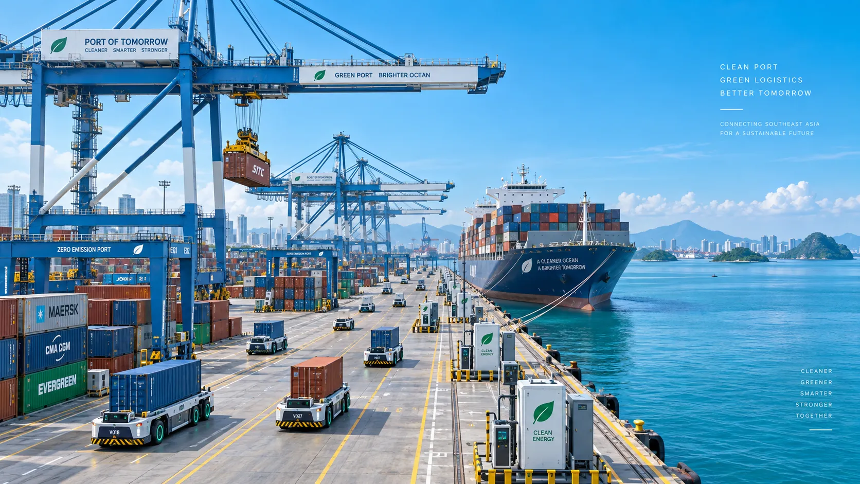
Smart Port Systems in Southeast Asia: Investment Priorities and Adoption Barriers
Smart port systems Southeast Asia: discover investment priorities, adoption barriers, and practical steps to build resilient, connected, high-performing terminals.

How to Evaluate Terminal Efficiency Solution Suppliers for High-Throughput Operations
Choose a terminal efficiency solutions supplier with confidence. Explore proven criteria for throughput, integration, lifecycle cost, safety, and reliable delivery.
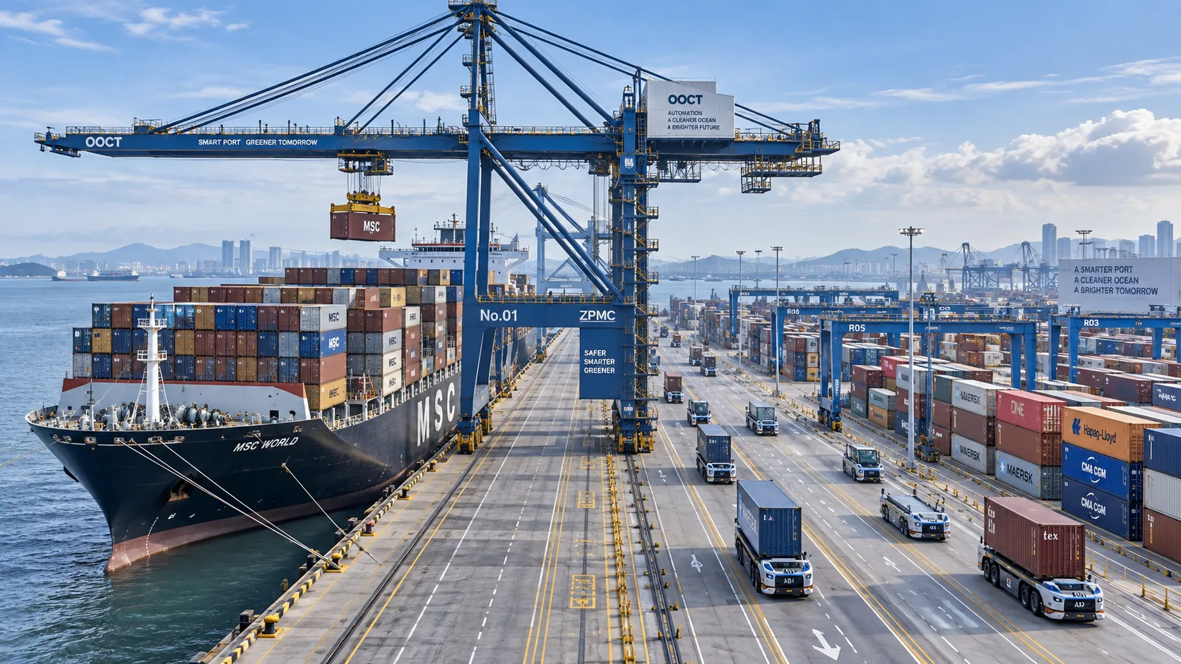
How to Specify a Quay Crane for Container Terminals by Vessel Size and Throughput?
Quay crane for container terminals: learn how to match outreach, lift height, capacity, automation, and cycle performance to vessel size and throughput goals.
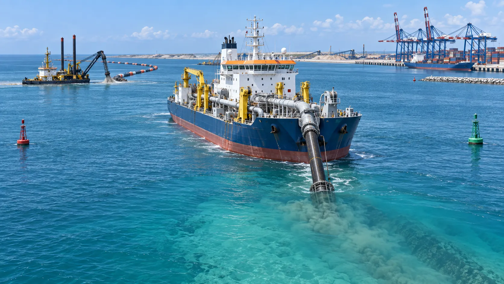
What Dredging Equipment Is Needed for Channel Deepening?
What dredging equipment is needed for channel deepening? Explore dredgers, pipelines, survey tools, and planning strategies for safer, more efficient port access.
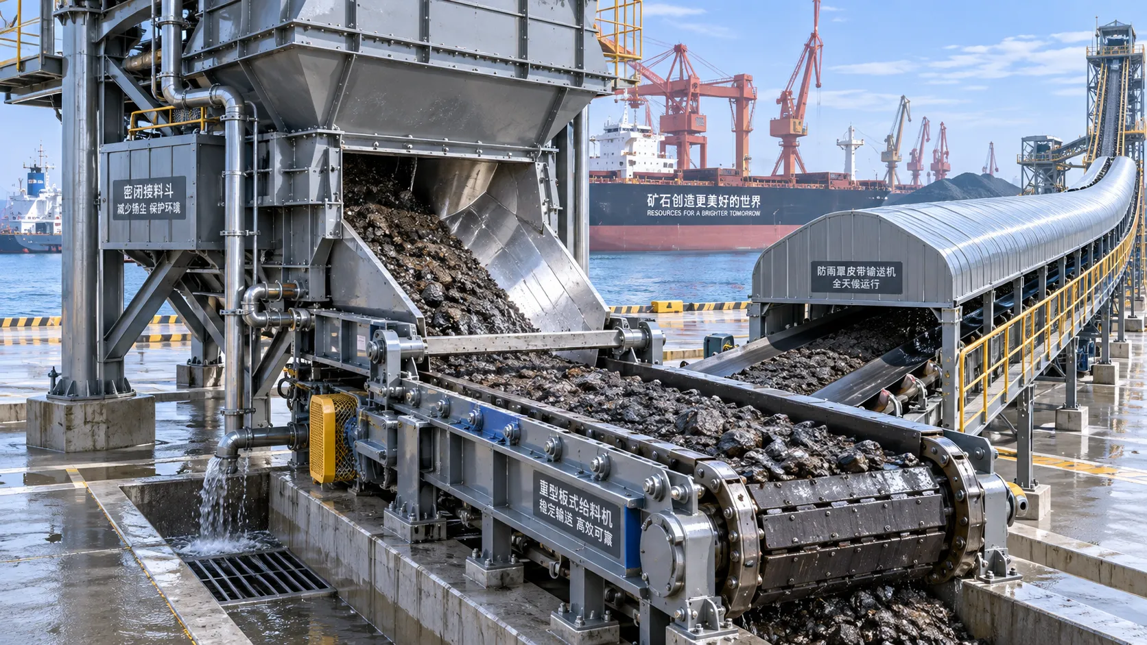
Which Bulk Handling Equipment Suits High-Moisture Cargo?
Which bulk handling equipment suits high-moisture cargo? Compare belt, apron, screw, drag, and slurry systems for reliable flow, less carryback, and higher terminal uptime.
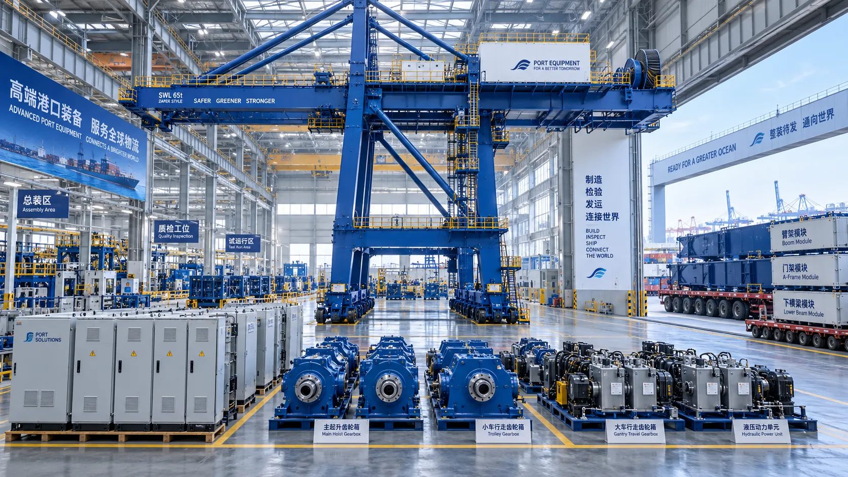
How Can Port Equipment Lead-Time Risk Be Managed?
How can port equipment lead-time risk be managed? Explore practical strategies to control critical paths, suppliers, transport, site readiness, and commissioning delays.
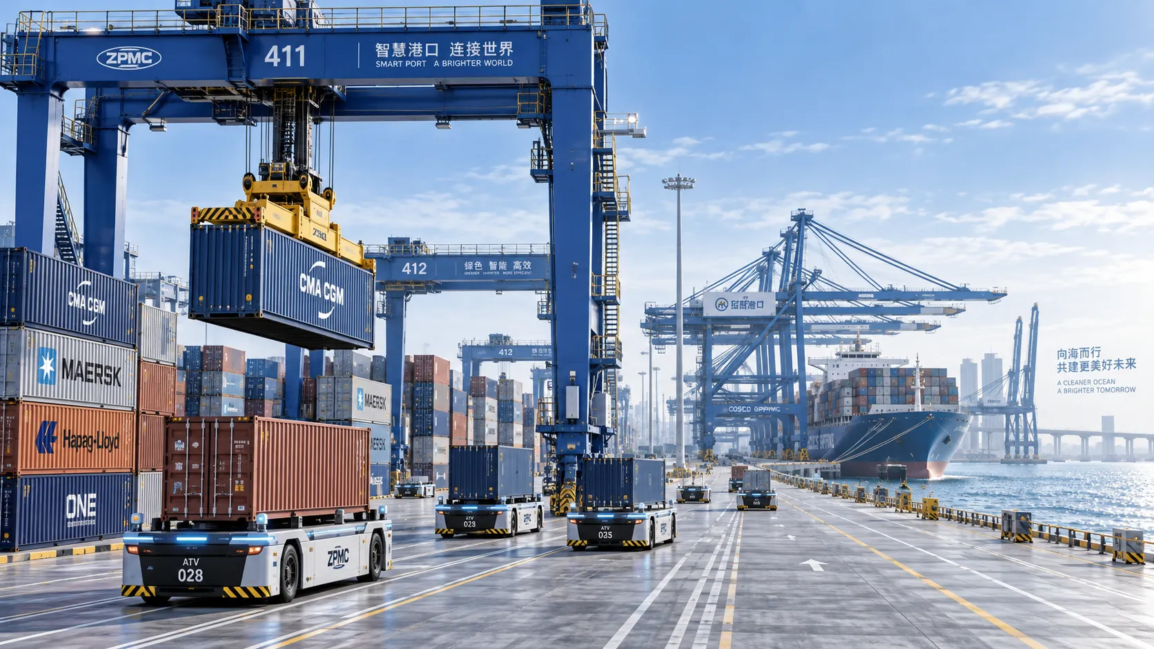
Terminal Automation Technologies That Raise Container Throughput Without Yard Disruption
Terminal automation technology that increases container throughput without disrupting yard flow. Explore smarter integration, resilient workflows, and phased deployment strategies.

Middle East Port Automation: Key Market Drivers, Projects, and Investment Risks
Port automation systems Middle East: explore market drivers, flagship projects, integration challenges, and investment risks shaping smarter, resilient terminals.
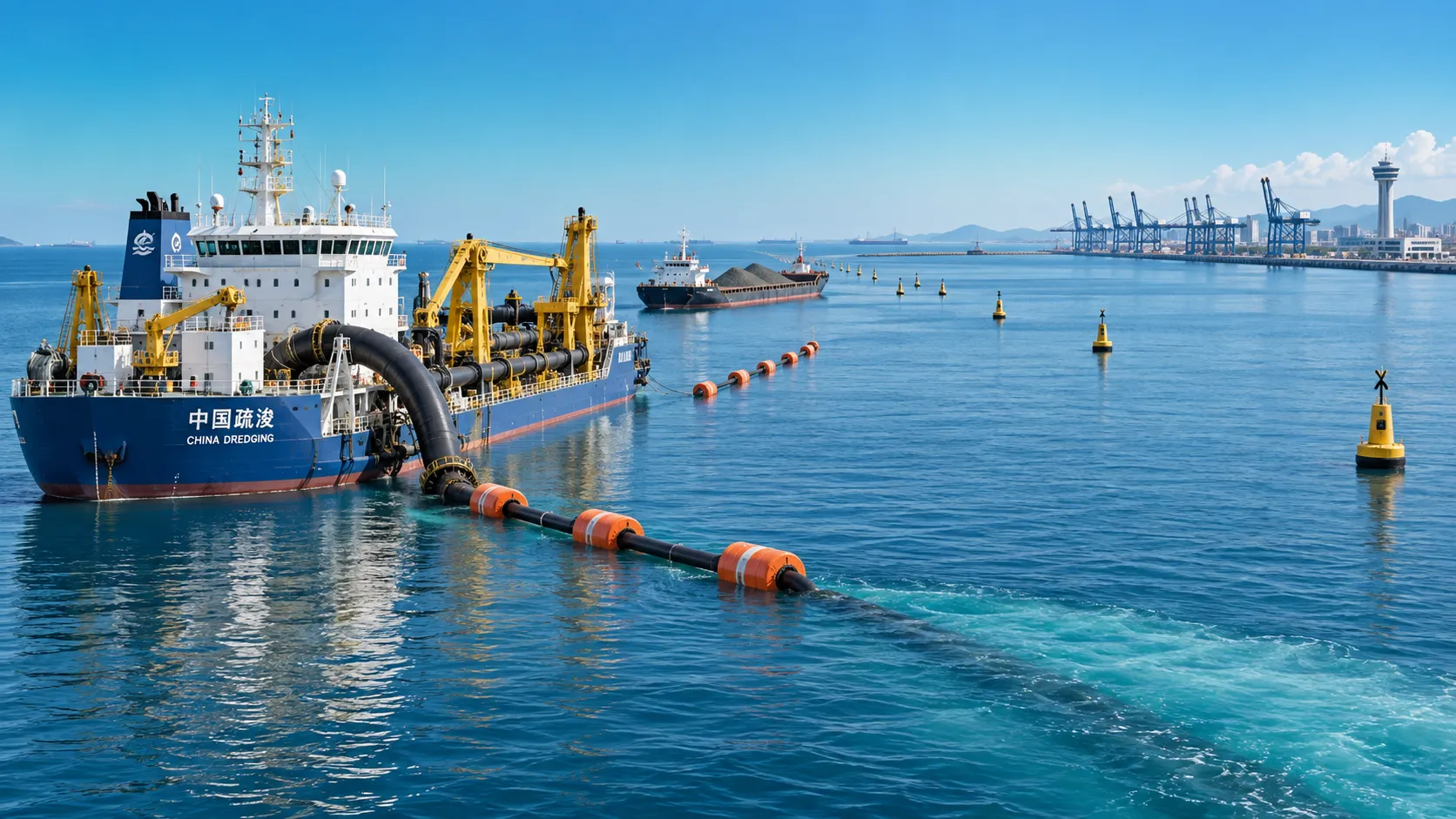
Planning Offshore Dredging Operations: Key Risks, Methods, and Project Controls
Offshore dredging operations demand smart planning. Explore key risks, proven methods, environmental controls, and project strategies for reliable delivery.